Definition Of Gravity Toolface
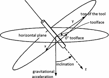
Gravity toolface is the angle of the borehole survey instrument within the wellbore measured clockwise relative to up and in the plane perpendicular to the wellbore axis. Gravity Tool Face - How is Gravity Tool Face abbreviated.

Magnetic And Gravity Toolface And How To Interpret The Meaning For Directional Drilling Drilling Formulas And Drilling Calculations
Science medicine engineering etc.

Definition of gravity toolface. 3 monitoring of the azimuth and inclination during the drilling process. The magnetic toolface reading is whatever magnetic direction the toolface is pointed. A processor 402 a may be in communication with the sensor.
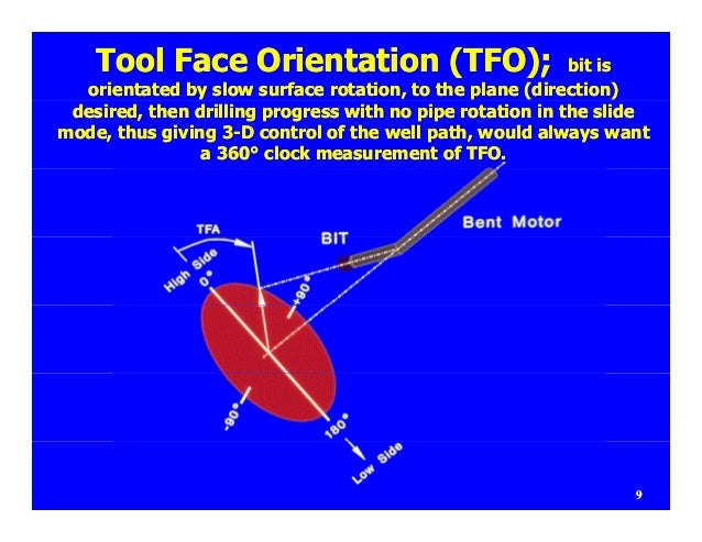
The reference of the GTF is the high side of well bore meaning the GTF shows 0 the tool face is aligned towards high side of well bore. The sensor assembly may comprise three accelerometers and an angular rate sensing device. Using gravity somewhat and a sharp directional change in either direction will aid in the process.
The high side maximum build maximum right low side maximum drop and maximum left directions have gravity toolface angles of 0 90 180 and 270 respectively. It is used in well sections which have an. George Town Festival Penang.
Looking for abbreviations of GTF. Gravity tool face is the angle between a tool reference axis and gravity in a vertical plane used when the hole is inclined greater than approximately 8º. The angle between high-side and toolface.
Exercise extreme caution when exiting out of casing. An example may comprise a downhole tool 300 and a sensor assembly 330 340 350 disposed in a radially offset location within the downhole tool. This scenario allows a greater ability to return to either wellbore.
For more-deviated wells the top of the borehole is the fixed reference and the angle is the gravity toolface or high side toolface. GTF stands for Gravity Tool Face. The natural or nuurmade feature to be negotiated mwt be characterizd in terms of its existent physical dimmsions as the possibility for zuch parameters to change with the passage of time.
And 4 the orientation of deflection. Grid convergence G Formula. IeGTF Tool Highside Angle - Declination Toolface Offset 180 Down Directional surveying permits 1 the determination of bottom hole location relative to the surface location or another reference system.
Also known as high-side toolface. The toolface is the direction where the drill bit side force acts. Drilling The angle measured in a plane perpendicular to the drillstring axis that is between a reference direction on the drillstring and a fixed reference.
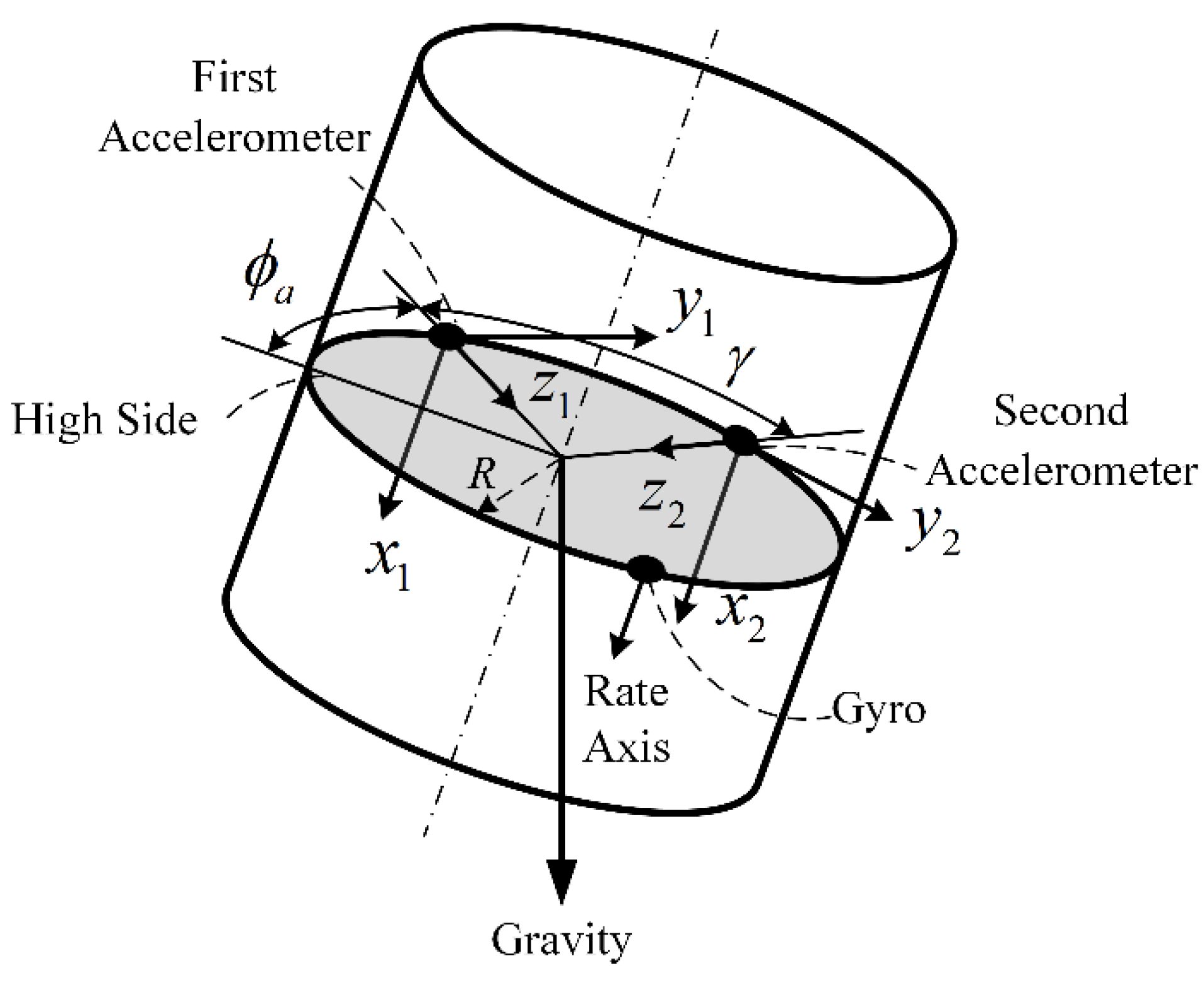
The gravity or high side tool face is measured from the high side of the borehole in a plane perpendicular to the hole axis. A curvature is obtained as the result of the axial penetration rate combined with the lateral penetration rate. For near-vertical wells north is the fixed reference and the angle is the magnetic toolface.
As you can see from the above image GTF is fairly simple and easy to understand. Gravity Tool Face listed as GTF. Systems and methods for determining gravity toolface and inclination are described herein.
GTF - Gravity Tool Face. - definition of the obstade to be crossed. ATN AGN D The angular correction converting azimuth readings of Grid North to True North.
2 the location of possible dog legs or excessive hole curvatures. Tool face angle To control the direction of borehole deflection the tool face angle must be calculated set during orientation and kept constant while drilling. This definition appears rarely and is found in the following Acronym Finder categories.
Magnetic tool face is the angle between the tool reference axis and magnetic north in a horizontal plane used when the hole is inclined less than approximately 8º. Gyroscopic tools may be used to measure azimuth where the survey is measured in a location with disruptive external magnetic influences inside casing for. It is Gravity Tool Face.
GTF is defined as Gravity Tool Face rarely. Gravity toolface is the angle of the borehole survey instrument within the wellbore measured clockwise relative to up and in the plane perpendicular to the wellbore axis. The high side maximum build maximum right low side maximum drop and maximum left directions have gravity toolface angles of 0 90 180 and 270 respectively.
A setting of approximately 125º either left or right toolface will work. In directional wells the gravity tool face is defined as the angle between the x-axis and the line intersect between the x-y plane and the vertical plane parallel to the tool axis. Gravity Tool Face or GTF is usually used in wells with more than 5deg inclination.
Gravity Tool Face It is the angular distance that a bent sub scribe line is turned about the tool axis relative to the high side of the hole.
The Toolface Dial Elements Of Directional Drilling
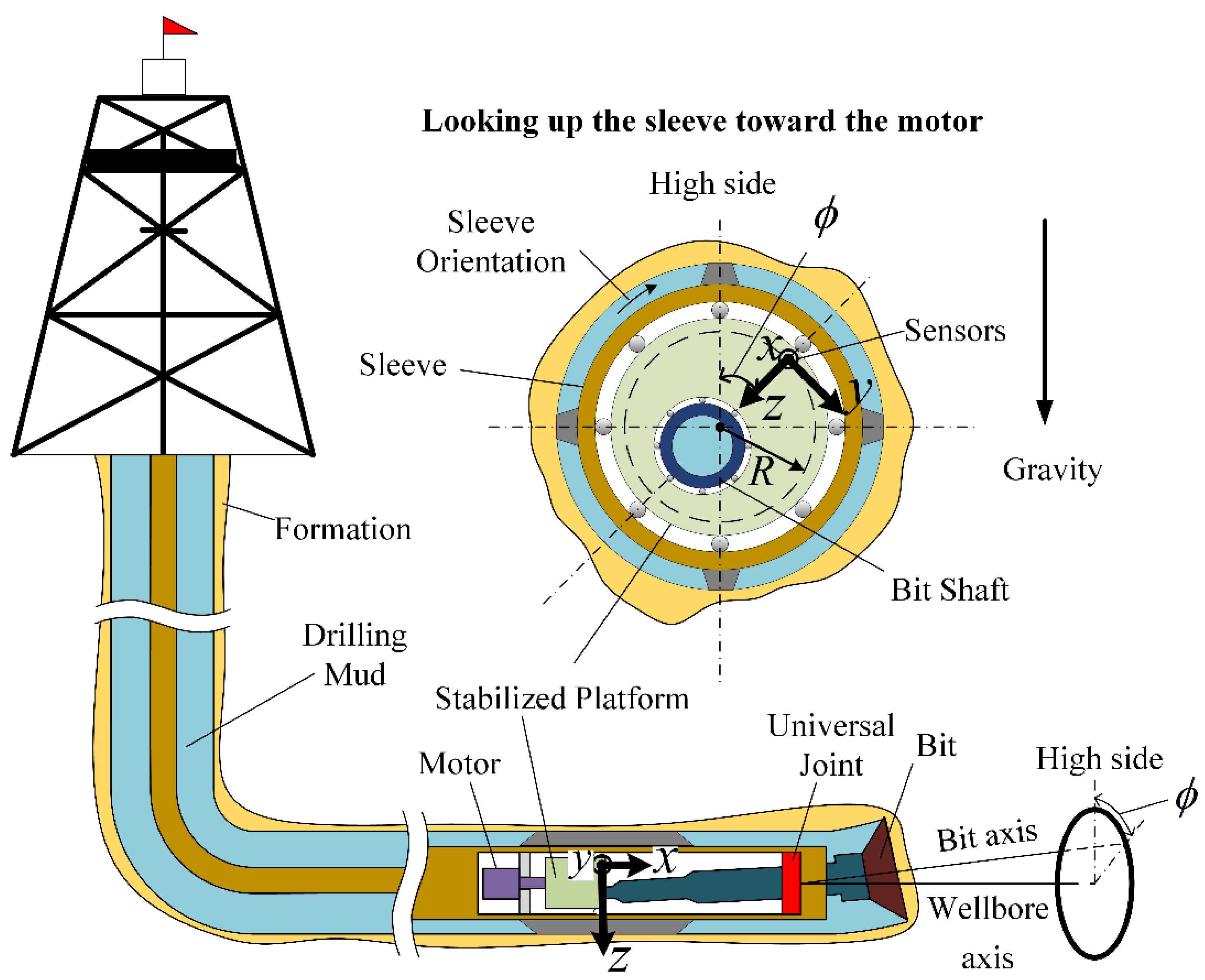
Sensors Free Full Text Dynamic Toolface Estimation For Rotary Steerable Drilling System Html
Magnetic And Gravity Toolface And How To Interpret The Meaning For Directional Drilling Drilling Formulas And Drilling Calculations

How To Know In Layman S Terms The Difference Between A Magnetic And A Gravity Tool Face In Directional Drilling And At What Angle Is The Crossover Between A Magnetic And A Gravity

Magnetic And Gravity Toolface And How To Interpret The Meaning For Directional Drilling Drilling Formulas And Drilling Calculations

Development Of A Directional Resistivity Logging While Drilling Tool Using A Joint Coil Antenna And Its Geosteering Applications Geophysics
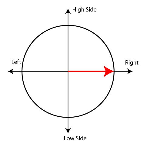
Magnetic And Gravity Toolface And How To Interpret The Meaning For Directional Drilling Drilling Formulas And Drilling Calculations

How To Know In Layman S Terms The Difference Between A Magnetic And A Gravity Tool Face In Directional Drilling And At What Angle Is The Crossover Between A Magnetic And A Gravity
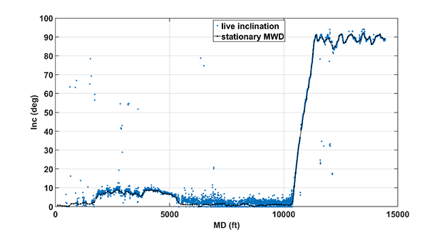
High Density Survey Data Allows For Capture Of Live Inclination Azimuth Delivers Clearer Downhole Picture Drilling Contractor

Gravity Tool Face Defined Youtube
Initial Calibration Of Mems Accelerometers Used For Measuring Inclination And Toolface Springerlink
Sensors Free Full Text Dynamic Toolface Estimation For Rotary Steerable Drilling System Html

Formulae In Practice Borehole Planning And Toolface Calculation Coring Magazine

A Azimuth And Inclination When Drilling A Directional Well B The Download Scientific Diagram

Magnetic And Gravity Toolface And How To Interpret The Meaning For Directional Drilling Drilling Formulas And Drilling Calculations
Directional Drilling System With Eccentric Mounted Motor And Biaxial Sensor Patent 0562147



Post a Comment for "Definition Of Gravity Toolface"